Coupling IOs
The binding or coupling between read and written value from a driver makes it possible to write to the variable also from other sources than from a PLC. Coupling of IOs is supported only when “Autogen” is used. If the automatic generation of variables is not used, datapoints for read and write can be manually mapped to common variable. Datapoint for reading would have this variable mapped in column IO/ST and data point for writing in column ST/IO.
As an example, we use a room unit. The setpoint will be controlled according to a time scheduler in the PLC, and if the user changes the setpoint using the knob (manual intervention), it will temporarily override the scheduled value. The next setpoint change follows at the time of the next time scheduler change. If there would be no coupling, users would not be able to intervene manually, as the setpoint value would be permanently overwritten by the scheduled value.
In the PLC there is a communication channel with a device inserted, containing inputs and outputs. The coupling is added by clicking the “Add couple” button.
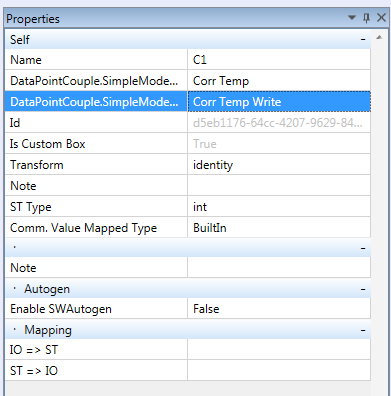
The new couple is saved as “C1”.
In the couple settings, change its name, enable Autogen, and set the target project to generate the variable to. Then assign the input which wil be read from, and output which will be written to. Remember to set the variable data type.
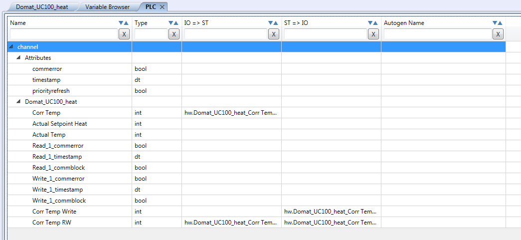
Autogen created the variable and mapped it into the device.
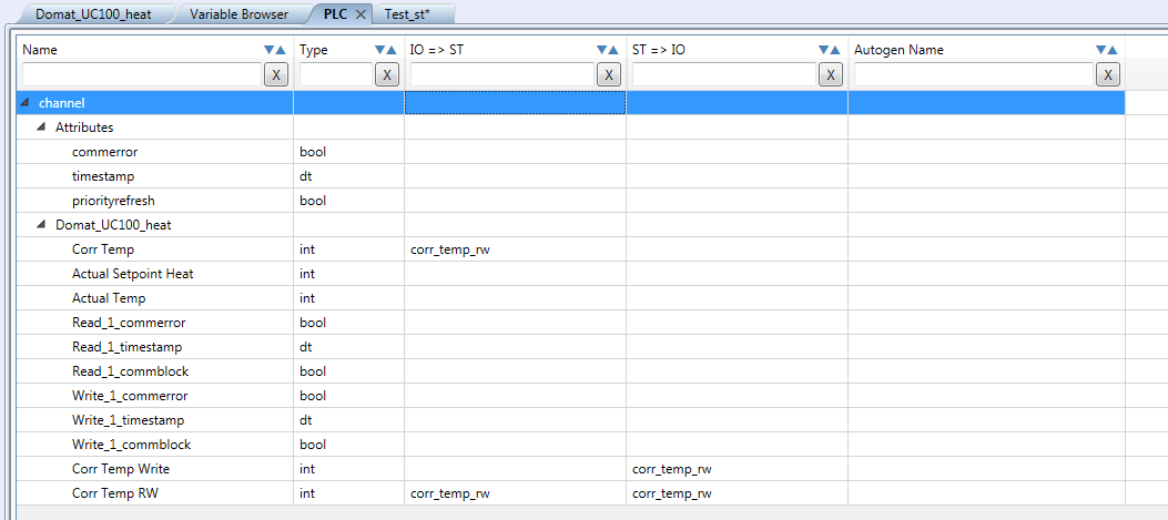
If you want to assign the varible manually, you must do the same as Autogen did. Read the value at the input, write it at the output, and read + write at the couple.
Note that if you bind variables from different registers, the PLC value is displayed as read value, and the output behaves as last value written from PLC (the output may not be the same as debug value). The couple can not be used to connect input and output internally. A couple can not substitute a “DO1:=DI1;” command, neither a direct “wired” link in FUPLA.


