K-Bus protocol driver
The K-Bus communication protocol is used for native communication of PLCs to I/O modules (cards, terminals) by Wago Kontakttechnik GmbH:
- The terminals on a K-Bus line are inserted in a row, into each other (by inserting into the previous terminal in the set). To terminate the bus properly, a terminating module 750-600 must be inserted at the end of the line.
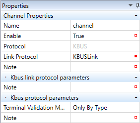
By adding a Wago PLC into a Mervis Solution, a channel with KBUSLink protocol is created automatically.
- Name - channel name, freely definable.
- Enable - a channel must be enabled (True) to communicate with the terminals.
- Protocol - select KBus
- Link Protocol - KBusLink (to communicate over KBus)
K-Bus link protocol parameters
- Terminal validation method (eg. full order code 750-451/000-009)
- Only by Type
- Type and Variant
- Type, Variant and Series
- Fields description
- Type - Code between first “-” and the “/” character (451 in the example above)
- Variant - Numerical marking after the “/” character at the terminal (000-009 in the example above)
- Series - Terminal series (750 in the example above)
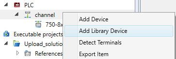
Right click the channel to open context menu. There are three ways how to add a device:
- Add device (not recommended, as all parameters have to be enterd manually)
- Add library device (recommended)
- Detect Terminals (only with an existing PLC connected to IDE)
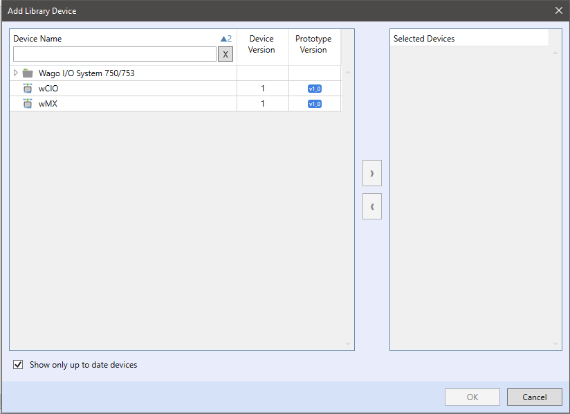
If the terminal types and their positions on the bus are known (e.g. from panel shop drawings), the easiest way is to add devices from library. Insert devices by right-click to channel and Add Library Device.
The device library contains predefined currently supported Wago terminals. Choose the device with higher prototype version and double click it, or focus it and click the right arrow button. Then click OK.
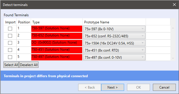
Terminal detection searches for all terminals connected to the K-Bus.
- connect to PLCwhich is connected to the terminal block
- right click the channel, Detect terminals
If the PLC is not in Commissioning mode, it changes to it automatically:
Detected modules are listed in the dialog window:
- Import - Import of the detected terminal
- Position - Position of the terminal on the K-Bus
- Type - Type of detected terminal (red colour indicates that the terminal is not added in the Solution yet)
- Prototype Name - Name of prototype (device) in the K-Bus library
Select the device to import and click Next. The selected devices are imported into your solution. The last way how to add a terminal into your solution is to create your own device - right click the channel, Add device.
Enter the Kbus parameters in Properties:
- Device position on bus - Position on the bus, starting with 1 from the main module to the right
- Device type - Select from the list. Virtual = terminal which is not physically on the bus, such as powering terminal, Special = specific module, such as user-defined module
- Device Type ID - Terminal type ID
- Device series - Unknown or Do not care (specific seriesa), Series 750 or Series 753
- Device variant (0..8) - Code after the “/” character of the order code
- Device variant - Extended - Extended variant of the device
- Data-in Area Size - Process image area in bytes
- Data-out Area Size - Process image area in bytes
- Password for Register Communication - Password necessary for writing to registers
- Diagnostics source - Not implemented in this version
- Channel count - Number of datapoints at the device (e.g. a terminal with 4 DI will have 4 channels)
- Power contacts - Types of contacts which link the terminals together
- Power consumption - Consumption in mA to monitor and check total terminals consumption
Open the device editor and add a Group (right-click to editor, Add Group). The group type is Read Only or Write Only, set it according to the terminal type. Then add a data point (right-click to editor, Add Data Point or hit the Insert key. In the data point properties, add the group the data point has to be attached to, Communication Value mapped Type (Bit (ST Type - bool), BuiltIn (ST Type - all data types and Array (ST Type - all data types and array length), Enable SWAutogen for automatic generation of global variables, or manual datapoint mapping IO ⇒ ST (read) and ST ⇒ IO (write).
KBus datapoint parameters
- Data Offset - Move n bytes from start of datagram
- Bit ofset - Move n bits from start of byte
- Byte Order - Reordering bytes from datagram to variable structure, standard setting is 12345678
- Byte Count - Number of read/written bytes
Configuration of analog I/Os
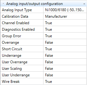
The analog I/Os are configured in the data point properties.
Diagnostics enabled - Measuring is enabled
- Calibration Data - Manufacturer (shifting of the curve) or User (upload of customer data - not implemented)
- Channel enabled - Measuring is enabled
- Overrange - Detection of the upper measuring range (e.g. at Pt1000 (-50..150 °C) higher value than 150 °C is detected
- User Overrange - Detection of the upper measuring range freely configurable by user
- Underrange - Detection of the lower measuring range (e.g. at Pt1000 (-50..150 °C) lower value than -50 °C is detected
- User Underrange - Detection of the lower measuring range freely configurable by user
- Wire Break - Detection of broken / disconnected sensor
- Short Circuit - Detection of short circuit at the sensor wiring
- Group Error - Group Error, not implemented in RT PLC
- Analog Input Type - Select the appropriate parameters according to the used sensor type. E.g. a Pt1000 sensor (-50..150 °C / 0.01) has measuring range of -50..150 °C, and transform Lib.Core.v1_0.Linear with parameters K: 0.01 (value after “/” at the temperature range) and Q: 0 (optional temperature correction)
- User Scaling - User scaling is not implemented in RT PLC.
To apply changes, upload the Solution to the PLC.
Export of devices at a K-Bus channel
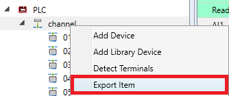
Export of the K-Bus devices at a K-Bus channel to CSV is useful for creating documentation. It can be performed by right click on the channel and selecting Export Item:
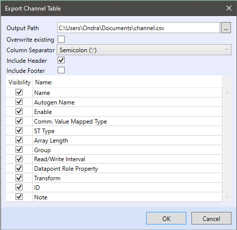
In the export dialog window select the output file path, to overwrite an existing file check the Overwrite existing option.
- Column Separator - Columns will be separated by the selected character - Semicolon “;”, Colon “,” or Tab “ ”
- Include Header - In the header the selected items will be listed - “Name” to “Note”
- Include Footer - In the footer the selected items will be listed - “Name” to “Note”
- Name - Name of the data points at the channel
- Autogen Name - Name entered for automatic variable generation, or mapped variable name
- Enable - If the channel is enabled for communication
- Comm. Value Mapped type - BuiltIn, Bit or Array
- ST Type - Selected data type
- Array Length - If the mapped type is Array, the array length can be exported
- Group - Communication group attached to this datapoint
- Read/Write Interval - How frequently the datapoint is updated at the bus
- Datapoint Role Property - Attribute - virtual variables (green background) or Data - physical data point
- Transform - Configured transformation
- ID - ID generated for this data point
- Note - Note at this data point
