M-Bus protocol driver
The M-Bus protocol driver is used for integration of meters, like electrical energy, water, heat meters…, which communicate over the M-Bus protocol. It must be distinguished between
- M-Bus as physical (hardware) standard - a two-wire bus which brings power to the meters, and which is used for communication between the master device and the meters
- M-Bus as a communication protocol, which can also be run on another bus type than M-Bus, e.g. over a RS232 serial line.
The PLCs in general do not provide physical M-Bus interface, and it is necessary to use a physical converter to connect M-Bus to the PLC, such as Domat M095 or M096. The converter connects to a RS232 interface, e.g. COM1 or COM2 at IPLC320. This COM port number is then entered in the driver properties.
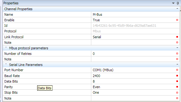
Right-click the PLC to define a new channel. Set its properties in the right part of the program window:
- Name - usually named according to the devices which are connected to the channel, or a bus in the project, e.g. “Heat_meters_South”.
- Enable - the channel must be enabled (True) in order to communicate.
- Protocol - select M-Bus
- Link protocol - Serial (to communicate over COM… ports)
M-Bus protocol parameters
- Number of retries - number of read attempts before the meter is considered as in communication failure
Serial Line Parameters
- Port Number - COM port number of the process station
- The following parameters must be identical both for the channel and for all the M-bus devices connected to this channel. The meters must be addressed and their baudrate must be set to the same value as here.
- Baud Rate- physical communication speed in bit/s, usually 2400 or 9600.
- Data Bits - number of data bits in a byte, M-Bus standard is 8.
- Parity - select communication parity here - None, Odd, or Even. M-Bus standard is Even.
- Stop bits - number of stop bits to indicate end of the transmitted byte. M-Bus standard is 1.
Right click the channel to open the context menu. There are four ways to add a meter:
- Create a M-Bus meter from real device
- Search M-Bus meters on network
- Add device
- Add device from library
If the meter type and its address are known, i.e. the bus has been (or will be) configured in advance by the meter supplier who provided a table with meters and their addresses, the Add device function can be used with Add Group and after a Group has been defined, Add data point (or more data points one after another, depending on how many values have to be read from the device). For this, the DIF/VIF parameters and value offset in the telegram must be known. These data are provided by the meter manufacturer. Therefore it is easier to follow these steps instead:
Create a M-Bus meter from real device
- connect to the PLC connected to the bus with meters
- right-click the channel, select Create a M-Bus meter from real device
- If the PLC has not been switched to Commissioning mode, it will be now:
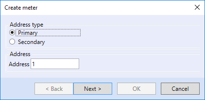
- select the way the meter will be detected: If meters are not addressed by primary addresses (1…250) yet, use Secondary addressing (meter serial number).
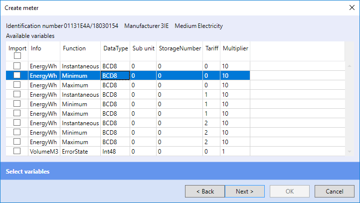
- at the detected meter, select the values to be imported, and click Next.
- PLC switches from Commissioning mode to previous mode, confirm by clicking OK.
- In the device list at the communication channel a new device appears, with the address and properties which were read from the real device on the bus.
- If there are more devices on the bus, and we need to detect them or just check the communication, use the Search M-Bus meters on network function:
- After switching to Commissioning mode,
- select the way meters will be detected. If meters are not addressed by primary addresses (1…250) yet, use Secondary addressing (meter serial number).
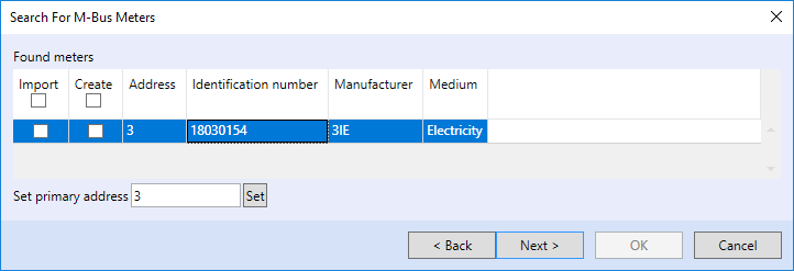
- The scanning process may take up more than 15 minutes, it depends on deployment of the secondary addresses in the whole address range. The detected meters are then listed in a table:
In this case, only a single meter was found on the bus.
(The dialog allows to change or set the meter primary address. This may ease the commissioning process - the meters are readdressed immediately after scanning, and no other software with serial to M-Bus converter is necessary. Meter addressing can be thus executed also on a remote basis, through PLC in Commissioning mode.
Check the meters to import in the Import checkbox. Unchecked meters will be ignored and not imported. Individual selection may be chosen if extra meters are added to an already configured bus. If all meters would be selected, all of them would be imported and some duplicate devices would appear on the channel.
If a meter of the same type is found in the M-Bus meter library, the device is taken from this library and predefined variables are imported. If a detected meter should be imported as an independent device and variables should be selected individually from all available variables read from the meter, check the Create box at this meter. The meters are then imported one after another with selecting of variables for every meter separately.
The Add device function inserts an empty device into the channel, and all its parameters must be entered manually. This is used when a meter with defined parameters must be created prior to access to a functional M-Bus.
Add device from library inserts a preconfigured meter device from the Mervis M-Bus library. This library will be extended in futore Mervis IDE releases. As of now, it is possible to save custom meters by right click to a meter and selecting Create library. After a meter is inserted., remember to set meter primary or secondary address and select the address type to be used for communication.
Inserting meters in a library
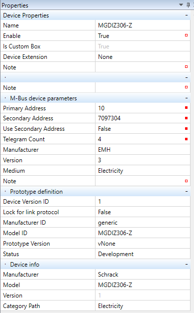
As soon as a meter device has been created and tested, its prototype can be added to the library, and used for inserting instead of creating a meter from real device. To save a prototype to library, properties in Prototype definition and Device information must be completed.
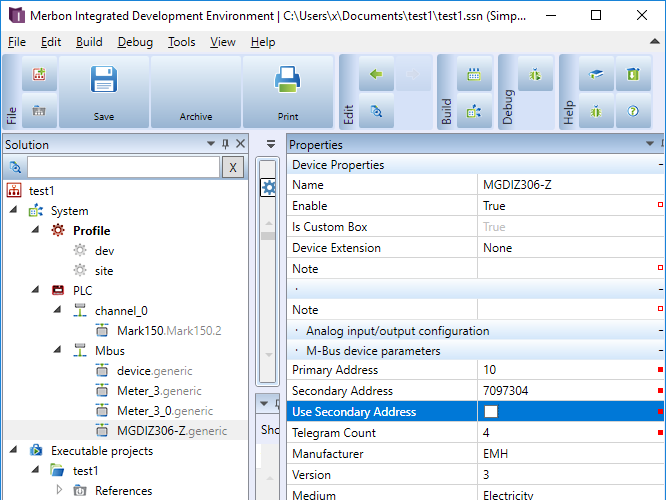
Device properties
- Name - a device may have a name for easier reference, such as Apt315Water
- Enable - the device must be enabled to communicate (set to True).
- Is Custom Box - Custom boxes can be edited. If a device is not a Custom box, it refers to a library.
- Device Extension - not used in this version.
M-Bus Device Parameters
- Primary address - M-bus address in range of 1…250. This address must be set on the device, which usually is provided by the supplier of the meter.
- Secondary address - long address entered by the device manufacturer, mostly same as serial number of the meter. It is not usually changed, although can be using special tools.
- Use secondary address - if True, secondary address is used for communication rather than primary address.
- Telegram count - not necessary to change if autodetection used.
- Manufacturer - standardized 3-letter short of the manufacturer name
- Version - whole number, value type byte
- Medium - select from one of the media types predefined in the M-Bus standard
Prototype definition
- Device version ID - free definable, version of the Modbus device in Mervis IDE
- Lock for link protocol - must be False
- Manufacturer ID - free text, identification of the device manufacturer, a 3-letter code according to the DLMS flag list is recommended (https://www.dlms.com/flag-id/flag-id-list)
- Model ID - free text, identification of the device type (there may be more device types designed for a single 3rd party hardware, with different variable sets etc.)
- Prototype version - version formatted vX_Y
- Status - selectable, development stage can be entered here (Development, Test, Release, Obsolete, Broken (= a branch separated from the main development branch)).
Device info
- Manufacturer - free text, identification of the device manufacturer
- Model - free text, identification of the type of hardware
- Version - free text, firmware version of the device (different firmware versions may require different devices in IDE, based on their memory maps)
- Category path - the path that is displayed in the “Add device from library” dialogue, it is used for better structuring of the device list in IDE.
Manual adding of meters and values
Apart from detection of M-Bus meters on the bus and automatic parsing of values, it is also possible to add values manually, in the same way as with other protocols. This brings more flexibility at meters which use segmentation:
Some M-Bus meters may split the response into more telegrams because the maximum telegram length is limited to 255 bytes. This is called segmentation. The standard segmentation process starts with sending an initial request SND_NKE. The meter acknowledges the request, and resets its internal segment counter. However, the master does not know in advance how many segments will follow, and has no means how to learn this. The way out is to dedicate a bit (FCB) in the data request (REQ_UD2) and use it as an indicator of requirement of the next telegram. The meter keeps the last received FCB, and if it does not match with the currently received FCB, it sends the next segment, and increments the segment counter. The master keeps sending REQ_UD2 and resetting FCB to obtain the next segment of the response. The last segment ends with a specific DIF (0F) and the master stops sending requests.
According to the M-Bus standard, if the meter response consists of two telegrams only, the FCB may indicate directly the segment number. This means that for FCB=0 the meter always returns the first segment of the response, and for FCB=1 the second segment. It is not necessary to initialize the meter, the meter needs no internal segment counter, the last FCB status needs not to be kept in the meter memory.
This is useful to know if the meter is configured manually. A data poing Group in a Device represents a segment. The “Telegram Number” parameter in a group is the segment number.
- Name - freely definable
- Read/Write interval - at some meter types powered by batteries the communication may be limited to 1 - 2 requests per day. Set the interval to query the meter here. If the meters are completely powered over M-Bus or from another power source (such al electricity meters) the readings may follow immediately one after another, as fast as the bus load allows. Then keep the interval at 0ms.
- Telegram Number - segment number, see above
- Response Timeout - time for the PLC to wait for reply until a communication error is reported. Normally, keep the predefined value of 1.5 s.
- Response Structure:
- Variable structure: the meter responses are of variable length, containing more variables in a sequence. Segmentation may occur, and the FCB mechanism described above is used.
- Fixed structure: fixed length response, typically containing two counters only.
- Request selection: same as Variable structure, but a direct query for a particular segment is also allowed - no need to query all segments one after another using the FCB mechanism.
At the Variable definition in a Group, the most important parameters are DIF/VIF and Offset. They determine the position of the value in the telegram.
- DIF/VIF - enter data according to the meter documentation
- Offset - enter data according to the meter documentation
- Signed value - At cumulated values, such as energy, volume, etc. the value usually has no sign. Current values, such as temperature, may require to have set this attribute to True. Please check the meter manufacturer documentation or contact the Domat Control System support.
- Parse VIF - the VIF parameter is taken from the incoming telegram rather than from the value entered as the DIF/VIF parameter above. Try to use if the VIF parameter is not known, or the value is not read correctly.
