Analogue (real) memory
Block name
B105_ANALOGMEMORY
ST call
PROGRAM TEST_B105
  VAR
 REAL0, REAL1,REAL2,REAL3,RAL4,REAL5 :REAL;
  SAVE :BOOL;
 FB: LIB.CORE.V1_0.B105_ANALOGMEMORY;
    END_VAR
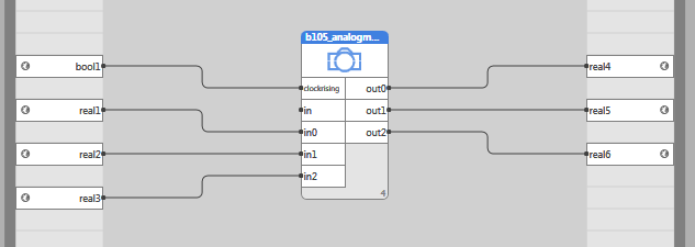
     FB(CLOCKRISING := SAVE, IN0:=REAL0, IN1:=REAL1, IN2:=REAL2, OUT0=>REAL3, OUT1=>REAL4, OUT2=>REAL5);
END_PROGRAM
Library
LIB\CORE
Version
V1.0
Description
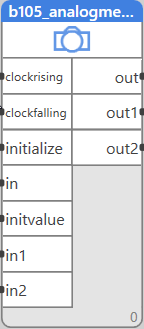
The block is a register of up to 16 real values. The values are stored at the rising (clockrising) or falling (clockfalling) edge of the input signal.
Inputs
| Input | Type | Description | Default value |
| CLOCKRISING | BOOL | Rising edge copies inputs to outputs. | False |
| CLOCKFALLING | BOOL | Falling edge copies inputs to outputs. | False |
| INITIALIZE | BOOL | If initialize = true, then the initvalue is written to all outputs | False |
| IN | MULTIIOREAL | Input array from the helper_multiinreal block | [0,0,…,0] |
| INITVALUE | REAL | The value set to all outputs when initialize = true. | 0 |
| IN0,IN1,..,IN15 | REAL | The inputs as individual values |
Outputs
| Output | Type | Description |
| OUT | MULTIIOREAL | Input array to the helper_multioutreal block |
| OUT0,OUT1,..,OUT15 | REAL | The outputs as individual values |
Function
The clockrising input reacts on the rising edge of the input signal which causes the inputs to propagate to the outputs. Similarly, the clockfalling input reacts on the falling edge of the input signal which causes the inputs to propagate to the outputs. If initialize = true, the initvalue is written to the outputs. Inputs and outputs may be connected in two ways, either through a multireal type to the in input, or individually to inputs in0,in1,….

