Modbus server setup
Modbus server provides data to a 3rd party PLC which is not compatible with the Mervis communication protocol. Both Modbus RTU (except for wPLC750-8101, mark1…, IMIO…, ICIO…) and Modbus TCP can be used for Modbus server.
In the example, two mark320 controllers will be connected over their COM4 ports where they will communicate over Modbus RTU, using Modbus address of 1, and register 1 to share data. PLC2 represents the 3rd party PLC (client PLC) which reads data over Modbus. PLC2 has a channel created, and a Generic device that reads a Modbus value from Register 1.
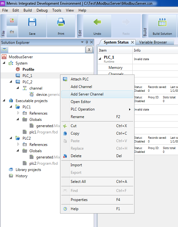
At the server PLC (PLC) add a server channel: right-click PLC and Add server channel.
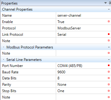
In Channel Properties, select ModbusServer, and link protocol Serial (master - slave, Modbus RTU server over a RS485/RS232 serial line) or TCP (client - server, for Modbus TCP server setup). In case of “Serial” enter the serial line physical parameters: COM port number (this port must not be used in the PLC for any other purpose, such as communicating with I/O modules),baudrate, number of data bits, partiy, and number of stop bits. For Modbus TCP, no other settings are necessary here.
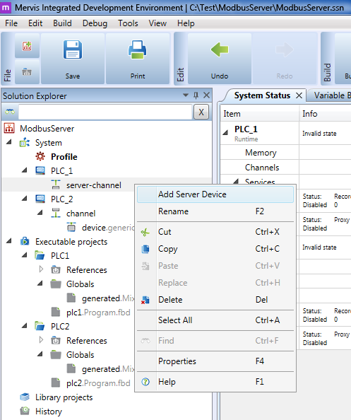
Add a server device into the server channel. For Modbus TCP, only one device is allowed.
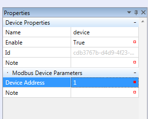
In case of Serial channel, enter only the Modbus link address (1…255) as Device address in the device properties.
In case of a TCP server, enter the IP address of the device. Normally, it is localhost (127.0.0.1)
“Device port” is standard 502, and “Device address” should be set to 1. The Modbus server editor consists of analogue (registers) and digital (coils) tabs.
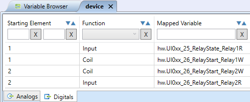
In the “Analog” tab, Holding registers (read/write) and Input registers (read only) can be added. In the “Digital” tab, Coils (read/write) and Inputs (read only) can be added. These functions are mutually independent, and the register numbers may overlap with the coil numbers.
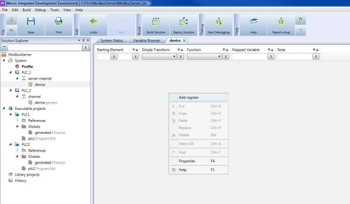
Right click the workspace to insert a new register or variable.
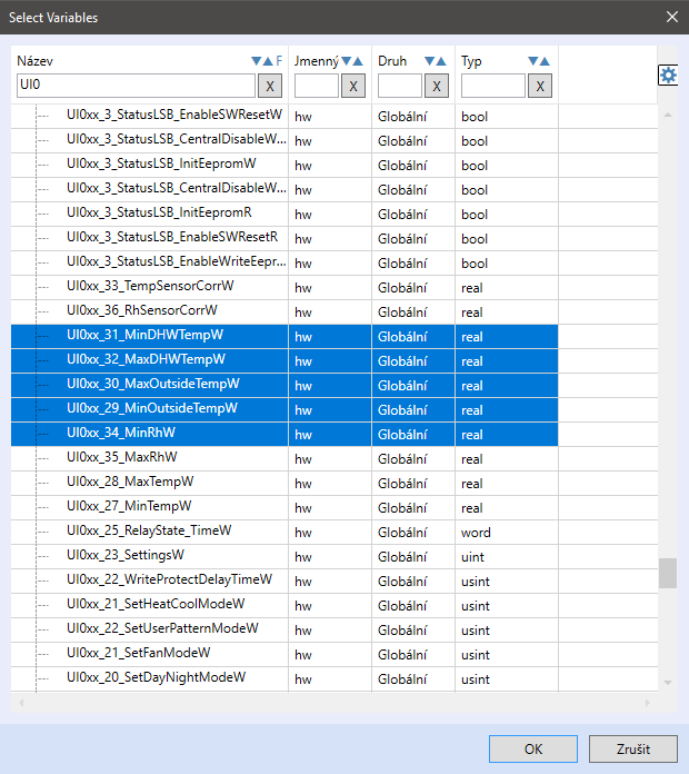
The “Add Variable” function allows selecting variables in the Variable browser, and multiple inserting into the Modbus server.
Analog functions (Holding reg. and Input reg.) and Digital functions (Coils and Inputs) may have the same “Starting element”, as these are different functions. Analog variables may be transformed before being brought into the Modbus table:
Convert to INT - Converting to Integer, use e.g. for Real variables.
Identity - Keeping the format unchanged.
Multiply by 100 - Value is multiplied by 100, and written to the Modbus table. This allows communicating e.g. temperatures as integers, a temperature of e.g. 23.56 °C is communicated as 2356, and must be divided in the Modbus client after reading. This is called a “HVAC integer format”.
Multiply by 10 - Same as above, multiplied by 10.
Divide by 100 - Value is divided by 100, and written to the Modbus table. May be used to fit long values into the 16-bit Modbus register.
Divide by 10 - Same as above, divided by 10.
After all required variables have been inserted into the Modbus table, deploy the solution into the PLC.
Note
For data types larger than 16 bits (1 register), 2 or more registers must be reserved in the Modbus table. E.g. a REAL value occupies 32 bits = 2 registers. Use the Identity transform then.
Example
The example below shows a Modbus server with starting element of 1, where the plc1 variable is mapped, as a Holding register. On the client side, the Modbus parameters must be set as Read / Write holding register No. 1. After deploy, the value can be changed on the client PLC and the changes are written into the server PLC.
Test the communication after deploying both projects. Entering a new value in plc1 results in change in the device_var1 variable.
Similarly, more variables can be enterd in a project.
