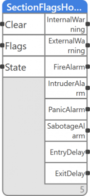
SectionFlagsHolder
Block name
SectionFlagsHolder
ST call
   PROGRAM TEST_SectionFlagsHolder
        VAR
            USINT1: USINT;
          SectionState1: SectionState;
            BOOL1,BOOL2,BOOL3,BOOL4,BOOL5,BOOL6,BOOL7,BOOL8,BOOL9: BOOL;
        END_VAR
     FB(Clear:= BOOL1, Flags:= USINT1, State:= SectionState1,
    InternalWarning:= BOOL2, ExternalWarning:= BOOL3, FireAlarm:= BOOL4,
    IntruderAlarm:= BOOL5, PanicAlarm:= BOOL6, SabotageAlarm:= BOOL7,
   EntryDelay:= BOOL8, ExitDelay:= BOOL9);
 END_PROGRAM
Library
LIB\JABLOTRON
Version
V1.0
Description
A variant of SectionFlags with enhanced functionality. A SabotageAlarm output is added along with an automatic sabotage detection –if sabotage is detected, the output is set to TRUE. The main addition is the hold function designed to hold alarms until a change in the STATE sector is detected. This means the block also requires a state input for the monitored sector. The block is also extended by the Clear optional input for the option to manually reset all alarms on hold by setting them to FALSE. This input is hidden, and its use is optional.
Inputs
| Input | Type | Description | Default value |
|---|---|---|---|
| Clear | BOOL | Rising edge resets all alarm outputs → sets them to FALSE | FALSE (hidden) |
| Flags | USINT | Current flags of the section | 0 |
| State | USINT | Current state of the section | Unknown |
Outputs
| Output | Type | Description |
|---|---|---|
| InternalWarning | BOOL | Internal alarm horn message |
| ExternalWarning | BOOL | External alarm horn message |
| FireAlarm | BOOL | Fire alarm |
| IntruderAlarm | BOOL | Intruder alarm |
| PanicAlarm | BOOL | Panic alarm |
| SabotageAlarm | BOOL | Sabotage alarm |
| EntryDelay | BOOL | Entry delay |
| ExitDelay | BOOL | Exit delay |
Function
The function block reads the Flags of the connected section. The value is transformed to individual bits according to a bitmask. Each bit is written on the corresponding output. The sabotage output is derived from the control module’s logic, where only Warning entries are active in the section’s flag. The fire, Intruder, panic and sabotage alarm outputs can have only TRUE value and are set to FALSE only after the section’s state changes, or the Clear input is set to TRUE (the input reacts to a rising edge).
Bitmask
| Bit position | Bit meaning |
|---|---|
| 1 | Internal Warning |
| 2 | External Warning |
| 4 | Fire Alarm |
| 8 | Intruder Alarm |
| 16 | Panic Alarm |
| 32 | Entry Delay |
| 64 | Exit Delay |
| 0 | Default flag value |
Application example
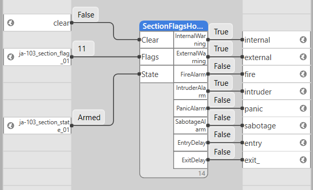
The Section_Flag variable read from the control module is connected to the Flags input. The Section_State variable read from the control module is connected to the State input. It is important for the section’s and flag’s numbers to match. The Clear input is a reset input intended for resetting alarm outputs. All outputs must be connected. Output values have multiple usages, such as indication via a web interface. Alternatively, they can be used as triggers for notification sending, or for activating security protocols of the facility.
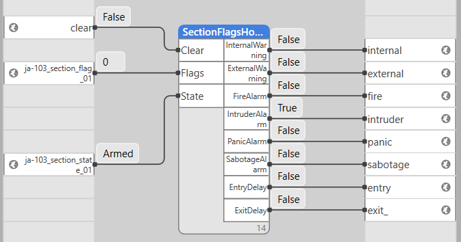
Alarm indication is held at TRUE even if the Flags input’s value is 0.
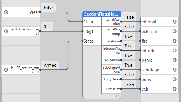
At this moment, the control module reported all alarm states. As we can see on the picture, the Flags input is no longer active, but the function block still holds all alarms at TRUE.
If the Clear input is set to TRUE at this point, or a section change is detected, all alarm outputs are set to FALSE, resetting the block back into its default state.


