PID controller
Block name
B36_PID_CONTROLLER
ST call
PROGRAM B36_TEST
VAR
   XIN,WIN,COOLING:REAL;
    FB: LIB.CORE.V1_0.B36_PID_CONTROLLER;
END_VAR
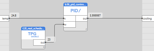
    FB(X:=XIN, W:=WIN, OUT=>COOLING);
END_PROGRAM
Library
LIB\CORE
Version
V1.0
Description
The block is an implementation of a PID controller (with parameters: P-band, Integration constant, Derivative constant, Offset, Min and Max values, and output value of an inactive controller).
Inputs
| Input | Type | Description | Default value |
| W | REAL | Setpoint (usually temperature). | 0 |
| X | REAL | Measured value (usually temperature). | 0 |
| CONTROLLERTYPE | CONTROLLERTYPE | Controller type (cooling/heating). | cooling |
| BP | BOOL | When set to TRUE, the I part is disabled (the controller acts as a P controller) | False |
| ENABLED | BOOL | Controller enable (FALSE = controller is deactivated). | True |
| XP | REAL | Proportional band | 30 |
| OFF | REAL | Offset, added to the setpoint W. | 0 |
| TI | REAL | Integration constant | 120 |
| TD | REAL | Derivative constant | 1 |
| MIN | REAL | Minimum output value OUT (usually 0). | 0 |
| MAX | REAL | Maximum output value OUT (usually 100). | 100 |
| DISVAL | REAL | Value of the OUT output when the controller is deactivated (ENABLED=FALSE) | 0 |
Outputs
| Output | Type | Description |
| OUT | REAL | Output signal (mostly valve or damper, 0 to 100%). |
| PFACTOR | REAL | P-part of the output signal |
| IFACTOR | REAL | I-part of the output signal |
| DFACTOR | REAL | D-part of the output signal |
Function
There is a control deviation at the controller input, E=(W+OFF)-X. The controller output OUT is given by the relation OUT=-100/Xp*(E+1/Ti*∫e+Td*e')+MIN, where the first part is the proportional part (P), the second part is the integration part (I), and the third part is the derivative part (D). The resulting value is finally limited by MIN and MAX, see figure at block B32. The I-part helps to achieve the exact control value.
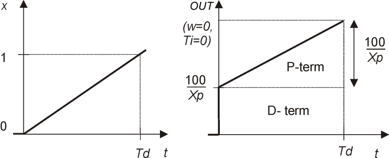
The D-part is calculated according to the figure below. To simplify the issue, let us assume Ti=0 and the I part = 0. When W+OFF=0 and the X input goes from 0 to -1 in time t=Td, then the D-part has a constant value of 100, and the P-band rises to 100/Xp.
The BP input sets the I-and D-parts to 0, if set to true.
The ENABLED parameter switches the controller off (ENABLED=FALSE, controller disabled, and OUT=DISVAL). Function in case of incorrect setting: Xp⇐ 0, then OUT=MAX for x>=W+OFF, and OUT=MIN for X<W+OFF. Note that the I- and D-parts are 0 in this case. If Ti⇐ 0 then the I constant is considered to be 0. If Td⇐ 0 then the D constant is considered to be 0. If MAX<MIN then OUT=MAX (minimum of both).


