Table of Contents
Three-point control
Block name
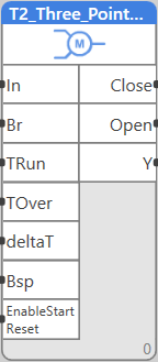
T2_THREE_POINT_CONTROL
ST call
PROGRAM TEST_T2
    VAR
        REAL1: REAL;
        TIME1,TIME2,TIME3: TIME;
        BOOL1,BOOL2,BOOL3,BOOL4: BOOL;
      FB: LIB.HVAC.V1_2.T2_THREE_POINT_CONTROL;
   END_VAR
 FB(IN:= REAL1, BR:= BOOL1, TRUN:= TIME1, TOVER:= TIME2, DELTAT:= TIME3, BSP:= BOOL2, CLOSE=> BOOL3, OPEN=> BOOL4, Y=> REAL1);
END_PROGRAM
Library
LIB\HVAC
Version
V1.2
Description
The block converts a 0…100 % signal to opening and closing pulses to control a three-point peripherial, such as a valve or damper actuator.
Inputs
| Input | Type | Description | Default value |
| BR | BOOL | Reset (sync) input to travel to a safe position and reset the internal position counter | False |
| BSP | BOOL | Safe position definition: TRUE = 100 % (open), FALSE = 0 % (closed) | False |
| DELTAT | TIME | Minimum duration of the output pulse | 2s |
| IN | REAL | Input signal, 0…100 % | 0 |
| TOVER | TIME | Extra travel time behind fully open or fully closed position for safe opening or closing | 3s |
| TRUN | TIME | Travel time between fully open and fully closed positions (0 to 100 % or back) | 65s |
| EnableStartReset | BOOL | When TRUE, block detects PLC reboot and ventil reset procedure is started at first cycle. Regulation according to IN starts afterwards. | True |
Outputs
| Output | Typ | Description |
| CLOSE | BOOL | Command to open |
| OPEN | BOOL | Command to close |
| Y | REAL | Expected (calculated) position (now equal to IN) |
Function
Before the output pulse is sent, the current input value is read and compared to the previous input value. If there is a difference (or, if there has been a change in the input signal IN since the last calculation cycle), the direction and length of the output pulse is calculated as a relative part of the total travel time, e.g. at a change from 15 to 20 % (i.e. by 5 %) and travel time of 65 s the pulse length is 5 / 100 * 65 s = 3.25 s, positive value means “open”. During the opening or closing time the algorithm does not react to the input signal changes.
If the calculated pulse time is shorter than the deltat value, it might mean that because of mechanical hysteresis the actuator would not move at all. The pulse is thus not generated, the required time is saved in the memory and the output is actuated as soon as the total cummulated pulse length exceeds the deltat value. Then, a single pulse of the totalized length is sent to the output.
If the input signal is > 99.9 %, the OPEN output is permanently on TRUE. If the input signal is < 0.1 %, the CLOSE output is permanently on TRUE.
The sync input, br, executes a synchronizing function: guaranteed travel to the safe state (most probably “close”) and reset of the internal block logics. The synchronisation should be executed e.g. once a day by bringing a rising edge to the BR input.
Application example
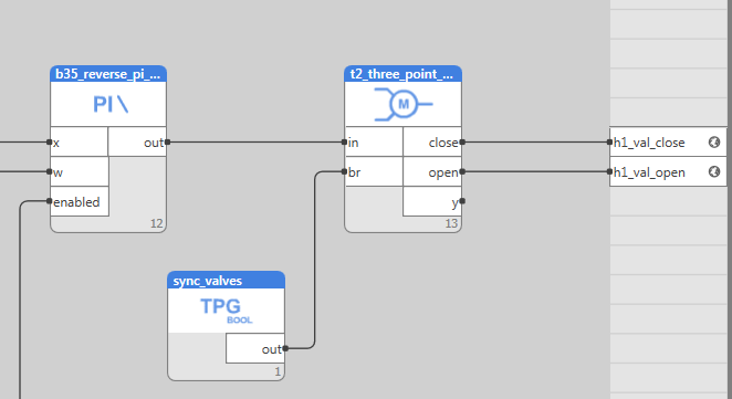
A three-point valve is controlled by a PI heating controller, B35. Its output signal of 0…100 % is converted to a three-point signal to control the binary outputs connected to the valve actuator, H1_VAL_CLOSE and H1_VAL_OPEN. Remember to set the correct parameters of travel time trun, deltat, and tover. The time scheduler generated a short signal (e.g. 1 min) once a day which causes the actuator to synchronize. (A single TPG can be used to synchrnize all actuators in a PLC which saves operation memory.)
Older versions
Versions V1.0, V1.1 are flagged as OBSOLETE. In some cases, expected position of valve on block could be different to real position of valve.

