Table of Contents
Pulse width modulation signal
Block name
B87_PULSE_WIDTH_MODULATION
ST call
PROGRAM TEST_B87
   VAR
 BOOL1,BOOL2 : BOOL;
 REAL1 :REAL;
    TIME1 : TIME;
   FB: LIB.CORE.V1_0.B87_PULSE_WIDTH_MODULATION;
   END_VAR
 FB(IN:= REAL1, ENABLED:= BOOL1,T:=T#10S,MIN:=0,MAX:=100,OUT=>BOOL2,TRES=>TIME1);
END_PROGRAM
Library
LIB\CORE
Version
V1.0
Description
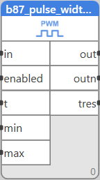
The block generates PWM (pulse width modulation) signal with variable duty time according to the input signal.
Inputs
| Input | Type | Description | Default value |
| IN | REAL | Input value | 0 |
| ENABLE | BOOL | Generator enable (true = running) | True |
| T | TIME | Signal period | 15m |
| MIN | REAL | Value for duty time = 0 % | 0 |
| MAX | REAL | Value for duty time = 100 % | 100 |
Outputs
| Output | Type | Description |
| OUT | BOOL | PWM output |
| OUTN | BOOL | PWM output negated |
| TRES | TIME | Remaining time to the end of the period |
Function
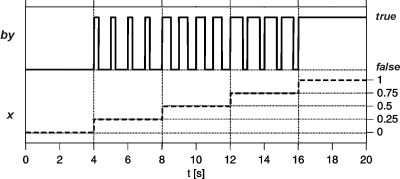
he block generates PWM (pulse width modulation) signal. The analogue input In is converted to binary pulsing signal with period of t. The input signal value is proportionally converted (for min ⇐ In ⇐ max). If In ⇐ min then out = false, if In >= max then out=true permanently.
The output outn is a negated value of out. The block also provides remaining time to the end of the current period tres.
The input enable sets out=false and tres=0, if set to False.
Function in case of wrong setting
Application example
The block is used as a signal generator for thermic valve actuators or electric heating bodies controlled by solid state relays. It is preferred to use dedicated I/O modules (Domat M312, M313). Do not use mechanical relays to control the power circuits as the number of switching cycles may be too high for mechanical relays.


