Table of Contents
Jablotron100 (JA-121T) Protocol Driver
A driver for communication with the Jablotron JA-121T module. Jablotron 100 is an RS-485 gateway for Jablotron 100 closed bus. In the Mervis IDE, the driver is named „Jablotron 100“. A Lib.Jablotron library is also included, albeit it requires to add a reference to it. The library contains SectionTransform transformation for sections, and SectionFlags and SectionFlagsHolder function blocks.
The library also features the SectionState enumerated type.
Using the SectionState enumerated type
ST
The SectionState enumerated type variable is defined by the Lib. Jablotron library.
Example of its usage in ST:
Declaration of a SectionState-type variable named State.
State : SectionState;
Writing a particular state into a variable:
State := SectionState#STATE;
FUPLA
For reading a particular state from the SectionState enumerated type, the EQ function block will serve the best. The IN1 input receives state value of the monitored section (Section_state), while the IN2 input is hidden with lib.jablotron.v1_0.sectionstate#STATE set as its default value.
Replace the STATE value (always placed after #) with the required SectionState state according to the table below:
| USINT | SectionState | Meaning |
|---|---|---|
| 1 | Ready | Ready |
| 2 | ArmedPart | Partially armed |
| 3 | Armed | Armed |
| 4 | Maintenance | Maintenance |
| 5 | Service | Service |
| 6 | Blocked | Blocked |
| 7 | Off | Unused |
| others | Unknown | Unknown |
SectionTransform
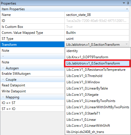
All prepared Jablotron device in Mervis IDE contains datapoints linked to state of section (section_state). All these section datpoints are configured to use transformation “SectionTransform”.
The SectionTransform transforms the internal USINT represenstation of the state of section into a Enumeration of SectionState type.
Datapoint defined in Mervis IDE for a Jablotron device is not available in the program, as it is only a definition of communication. To use it, you need to assign a variable of the corresponding data type. Alternatively, you can use the Autogen feature to create and assign variables automatically.
Communication channel
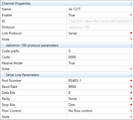
First, you need to create a communication channel determining which protocol and port will the PLC use to communicate with the Jablotron 100 control module. The JA-121T module communicates via RS-485 (8n1) interface at the speed of 9600 bps.
Channel Properties
- Name – the name is usually derived from the group of devices connected to the channel. In this case, the channel is reserved only for Jablotron devices, ie. „JA-121T“ or „Jablotron 100“
- Enable – must be set to TRUE to enable the communication
- Protocol – selects a communication protocol. Choose the „Jablotron“ option
- Link protocol – set to „Serial“
Jablotron 100 protocol properties
- Code prefix – order of users obtained from the control module (ie. maintenance = 0)
- Code – user’s access code
- Passive mode* – TRUE = the control module sends only responds to queries, FALSE = the control module sends data immediately without any prompts
- if you need to write data into the control module, set the option to TRUE (must correspond with ESS settings). Otherwise, leave it at FALSE
Serial line parameters
- Port number – substation COM port (choose any RS-485 port)
- Baud rate – communication speed in bits per second (bps). The module is set to 9600 bps
- Data Bits – number of data bits in a single byte (set to 8)
- Parity – sets even, odd or no parity - set to „none“
- Stop Bits – number of bits signalling the end of a transmitted byte (choose „One“)
Communication Channel Device
Right-click on the channel to display a context menu. You can add a definition for your version of Jablotron 100 ESS by clicking on Add Library Device. The device represents the maximum number of data points (sections, PGs, peripherals) available for the given Jablotron 100 control module variant. Only a single control module can be connected to a single serial channel.
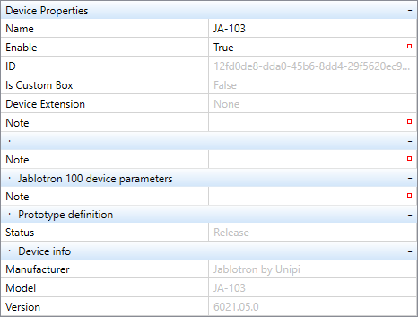
By selecting the device in Mervis IDE, its properties will be displayed in the right panel:
Device properties
- Name – the device can be named (ie. after the control module)
- Enable – for the device to communicate, it must be enabled
- Is Custom Box – displays if the device is from the library, or can be customized
Prototype definition
- Status – can be freely defined, serves as an indication of the current development status (Development, Test, Release, Obsolete, Broken, Unsupported)
Device information
- Model – freely customizable, displays the HW name
- Version – Version of the hardware, freely customizable
- Manufacturer – the name of the manufacturer, freely customizable
Groups of datapoints
By double-clicking the device, a panel will open for defining groups and data points in the device. The communication runs by datapoint groups. Within a single group (= a single read query), it is possible to send a query for the status of multiple or all sections, PGs or peripherals at once. The control module responds by sending the current status of all queried groups, PGs or peripherals. If used correctly, group communication does not cause any significant load on the bus. All peripherals are read, including the unused ones if not removed. Variables must be always assigned to a group.
However, using a multiple-datapoint group is not always the best way to go. For example, write groups use only a single-datapoint group by default.
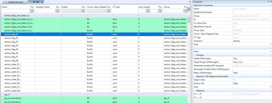
The selected Jablotron 100 library device has the maximum number of data points already defined. Group attributes are described below.
Group properties
- Name – name of the group, serves as variable identification
- DataPoint.SortOrder – order of groups displayed on the device’s screen (0,1,2, …, N)
- Read/Write Interval – determines how often the group will communicate. For continuous communication (eg. the shortest interval possible), set the value to 0ms. By default, the interval is optimized for the most effective communication (sector: 2s, PG: 5ms, peripheral: 5s)
- Is Custom Box – determines if the device is from the library or can be edited
- Group Type – a selection of group type (read-only group or write-only) group
Jablotron 100 group properties
- Object – which type of object will the group communicate with (sector, PG, peripheral)
- Use Selection from Query – TRUE = the group will send queries only to selected data points defined in the group, FALSE = the group will send queries to all control module objects in the selected group (including nondefined groups)
Datapoints
The next chapter describes definitions of data points into which the driver will load control module values collected from group communication.
Datapoint properties
- Name – name of the datapoint, a variable under this name will be saved into the program
- DataPoint.SortOrder – sort order of the datapoint within its group (0,1,2, …1, N)
- Read/Write Interval – if the interval is needed to be longer than the interval of the group the variable is assigned to, you can enter it into this line
- Is Custom Box – determines if the device is from the library or can be edited
- Group – choose a group to which the data point is assigned
- Group Type – will be filled automatically after selecting a read or write group
- Comm. Value Mapped Type – selection between BuiltIn, Bit and Array
- Bit – for reading bool values
- BuiltIn – for reading any other value types. The exact type is to be specified in the Type ST field.
- Array – for reading value array into an array variable
- Type ST – a selection of variable type. This creates a variable with a specific type – this step can be skipped if a transformation is applied
- Transformation – between loading up values from the control module and writing them into a variable, it is possible to transform the values. Jablotron protocol allows a transformation of sector states from usint to string, using format corresponding with control module’s sector state names. This transformation has multiple uses, such as displaying sector lists on the HMI
Jablotron 100 datapoint parameters
- Object index – order of objects at the control module’s side (the numbers represent numbers of sectors, PGs and peripherals)
- Section info – determines whether a sector state or a sector flag will be written into sectors
Autogen
- Enable Autogen – enabling Autogen will automatically create global variables and map them to input and output variables. Global variables are required for any work with the program and are mainly used by FUPLA blocks. If the Autogen is not enabled, you need to create and map global variables manually. We recommend setting the Enable Autogen to TRUE
Mapping
- IO⇒ST – mapping an input variable to a global variable (“input-output → ST or FUPLA”)
- ST⇒IO – mapping a global variable to an output variable (“ST or FUPLA → input-output”)
Couple of datapoints
Defining couples to variables is also elaborated on here. Both read and write variables can be mapped to couples, creating a read/write variable.
Couple properties
- Name – name of the couple, serves as variable identification
- Is Custom Box – determines if the device is from the library or can be edited
- Comm. Value Mapped Type – same as datapoints type, which they are coupled with
- Type ST – will be filled out automatically once a datapoint type is selected (both read and write)
- Transformation – between loading up values from the control module and writing them into a variable, it is possible to transform the values. Jablotron protocol allows a transformation of sector states from usint to string, using format corresponding with control module’s sector state names. This transformation has multiple uses, such as displaying sector lists on the HMI
Couple
- Read Datapoint – select read datapoint
- Write Datapoint – select write datapoint
Autogen
- Enable Autogen – enabling Autogen will automatically create global variables and map them to input and output variables. Global variables are required for any work with the program and are mainly used by FUPLA blocks. If the Autogen is not enabled, you need to create and map global variables manually. You can learn more about Autogen in this article. We recommend setting the Autogen to TRUE
Mapping
- IO⇒ST – mapping an input variable to a global variable (“input-output → ST or FUPLA”)
- ST⇒IO – mapping a global variable to an output variable (“ST or FUPLA → input-output”)
Groups of write datapoints
The last important bit of info for successful configuration of communication with Jablotron 100 control module (write only) is to know the definition for writing data into the control module (sector state, PG).
Group attributes look like the following:
The difference between a read and a write group is, that the group type is WriteOnly and the group contains only two lines
- Write only with change – optimizes the serial communication, group query is sent only if any data point in the group is changed
- Logical OR to extending – a method of compiling an output buffer for writing into the device. By default, the data are inserted into positions determined by offsets and lengths (function for experts)


