Table of Contents
Modbus protocol driver
The Modbus protocol driver is probably the most frequently used driver. There are rich possibilities of Modbus datapoints configuration setting in Mervis IDE, and this is why we will have a look on the datapoint definition in more detail.
A datapoint defined in a Modbus driver is not available in the program, it is just a communication definition. In a program, we need variables to work with. Hence, it is necessary to map (attach) a datapoint to a global variable. This abstract enables the engineer to reconnect easily a variable from one datapoint (input or output) to another, e.g. in case of physical damage of an I/O module. Global variables can be created and attached to datapoints also on an automatic basis, using the Autogen function.
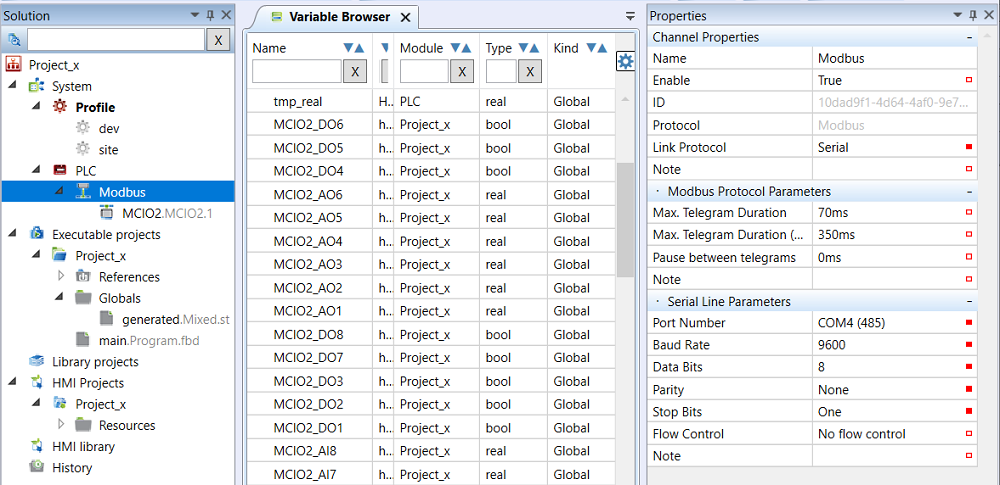
As a first thing, a communication channel has to be created. This is to specify on which physical port shall the PLC communicate to the Modbus server: a serial line (for Modbus RTU) or the Ethernet interface (for Modbus TCP) can be used.
Modbus Client Channel
- Name - usually named according to the devices which are connected to the channel, or a bus in the project, e.g. “FCU”, “Bus1”.Enable - the channel must be enabled (True) in order to communicate.
- Link protocol - Serial for Modbus RTU (over RS232 or RS485, i.e.on the COM… ports), Tcp for Modbus TCP over Ethernet.
- Integration mode - False: read telegrams are interlaced by write telegrams, launched on change of the written value. True: all data to read are read first, and then all data to write are written. This mode may be more useful for some 3rd party devices.
- Max. Telegram Duration - also known as Timeout. The Modbus device must respond to a request within this time. The span of 70 ms is OK with a reserve for Domat I/O modules, while for some 3rd party devices like PV inverters, VSDs, etc. a longer time of about 200…500 ms must be set. A span too long may slow down the whole communication if a device on the bus is offline and does not respond.
- Max. Telegram Duration (Commissioning) - this time, usually longer than the previous one, is used at the commissioning time when it is not necessary to optimize the communication, and errors caused by too a short timeout shall be avoided.
- Pause between telegrams - sometimes used for easier recognition of a telegram start by a 3rd party device. If there are communication dropouts, set this value to about 200…300 ms.
- Note that this parameter is not relevant for Modbus TCP, as the TCP connection timing requirements may be different for various 3rd party devices.
- Port Number - COM port number of the PLC.
The following parameters must be identical both for the channel and for all the Modbus devices connected to this channel. Please follow the 3rd party documentation. If the devices have selectable parameters, check if the settings correspond with the channel settings in the PLC.
- Baud Rate - physical communication speed in bit/s.
- Data Bits - number of data bits in a byte.
- Parity - select communication parity here - None, Odd, or Even.
- Stop bits - number of stop bits to indicate end of the transmitted byte.
These parameters have no meaning for Modbus TCP communication and are not displayed if Modbus TCP is selected.
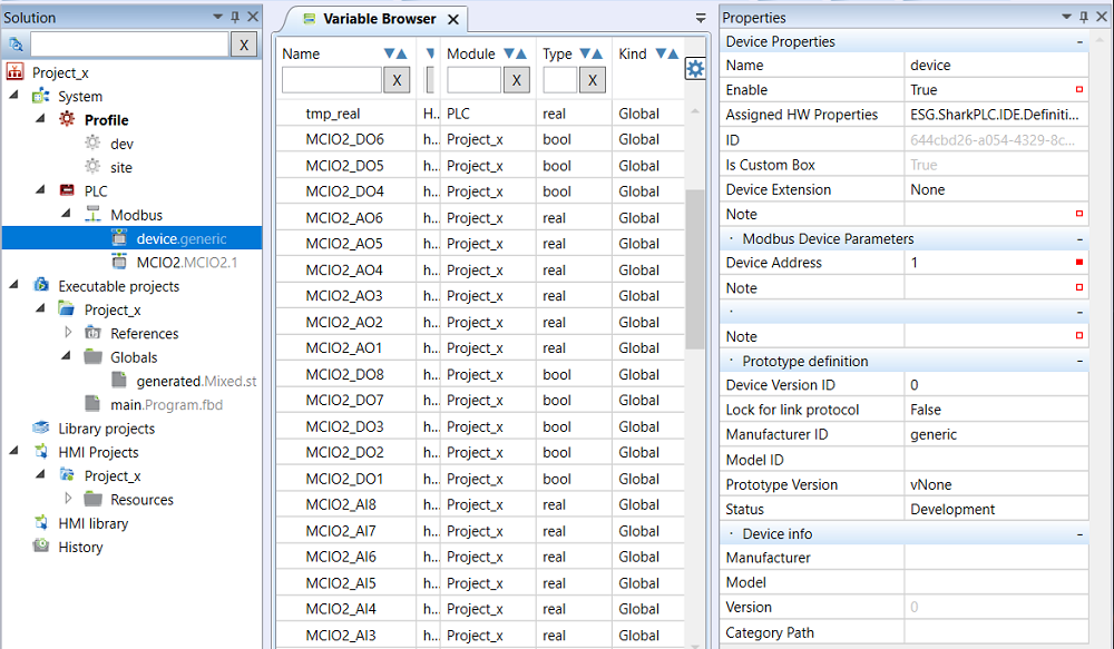
Right click the channel to add a Modbus slave (Device). A device is a Modbus server (Modbus address) with which we want to communicate, and contains Modbus registers. There may be up to 255 devices on a bus, however, maximum of 60 to 80 devices is used for easier commissioning and service. Now, set the device parameters:
Device properties
- Name - a device may have a name for easier reference, such as AHU1VSD1.
- Enable - the device must be enabled to communicate (set to True).
- Is Custom Box - Custom boxes can be edited.
Modbus Device Parameters
- Device Address - Modbus address 1…255. This address must be set at the device, which is arranged typically by the device hardware supplier.
Prototype Definition
- Lock for link protocol - must be False
- Manufacturer ID - free text, identification of the device manufacturer
- Model ID - free text, identification of the device type (there may be more device types designed for a single 3rd party hardware, with different variable sets etc.)
- Status - selectable, development stage can be entered here (Development, Test, Release, Obsolete, Broken (a branch separated from the main development branch)).
- Version ID - free definable, version of the Modbus device in Mervis IDE
Device info
- Manufacturer - free text, identification of the device manufacturer
- Model - free text, identification of the type of hardware
- Version - free text, firmware version of the device (different firmware versions may require different Modbus devices in IDE, based on their Modbus maps)
- Category path - the path that is displayed in the “Add device from library” dialogue, it is used for better structuring of the device list in IDE.
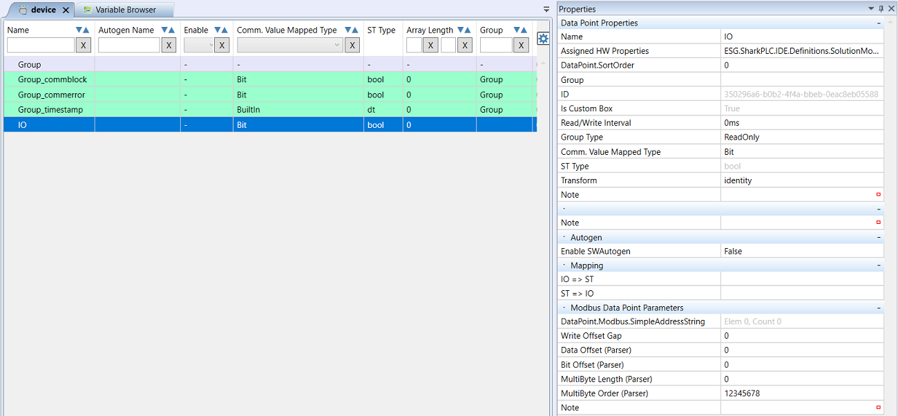
Double click the device to open a workspace for Groups and datapoints definition in a device. The Modbus communication follows in groups of datapoints. There are more consecutive registers communicated within a single Group (which is one Modbus request for reading or writing). Group communication optimizes bus traffic and speeds up the data transfer rate. Datapoints are always defined as members of a particular Group.
Firstly, define a Group for reading of registers. This is necessary even if only a single register has to be read.
- Right click the workspace with the device name to open the context menu
- Select Add Group
- Enter the Group parameters:
- Name - name of the group, such as “Temperatures_reading”. The name should reflect the common properties of the registers which are contained in the Group.
- Read/Write Interval - how often should the Group communicate. Enter 0 ms for communication without gaps.
- Group Type - select between ReadOnly (a Group which reads data from the device) and WriteOnly (a group which writes data to the device).
Modbus Group Parameters
- Starting Element - number of the first register to read
- Function - Modbus function which must fit with the Group type: for ReadOnly groups choose some of the Modbus Read functions, for WriteOnly groups select some of the writing functions. The function must be supported by the device - check in the Modbus server documentation.
- Quantity of Elements - number of registers or coils to be read or written in the Group.
Example: A Group must read Modbus registers 11 to 15. The Group parameters will be set as follows: Starting Element to 11, Quantity of Elements to 5.
Secondly, the datapoints will be defined, to which the driver reads values from the Group communication.
- Right click the workplace to open the context menu
- Select Add Data Point
- Enter the datapoint parameters:
- Name - Datapoint name which is used for its identification in Mervis IDE
- Assigned HW Properties - special parameters used e.g. at I/O modules. They are not used when integrating 3rd Party devices.
- Group - select a group the data point belongs to.
- Read/Write Interval - if the communication interval for this datapoint should be longer than that of the Group, enter it here.
- Group Type - fills in automatically after a Group is selected (read or write)
- Comm. Value Mapped Type - select from BuiltIn, Bit and Array.
- Bit - select if a bool value has to be read.
- BuiltIn - select if value of any other type has to be read. The type will be specified in the ST Typeparameter.
- Array - select if the values have to be read into an array date type (Array).
- ST Type - select the data point type. If no transform (see below) is used, the data type must be of the same size as the Modbus table range to read from, specified in the Modbus data point parameters. List of available data types is in the elementary data type table.
- Transform - Between the readout of a register value over Modbus and writing it into a data point it is possible to recalculate, or transform, the value. It is used for example with analogue values in HVAC Integer format, i.e. decimal numbers multiplied by 10 or 100. Example: a temperature measured in the device is 21.5 °C, and the Modbus server transmits it as 2150. This value read from the Modbus register must be transformed back - divided by 100 using a linear transform.
These are the predefined transformations
- Identity - the value is not transformed, it is written as is
- Resistance to temperature - linearisation curve for Pt100, Pt500, Pt1000, Ni1000-5000, Ni1000-6180 sensors. The transform has following parameters:
- Kind - sensor type which determines the predefined linearisation curve
- Pre_K - first linear pre-linearisation transform y = Kx + Q coefficient
- Pre_Q - first linear pre-linearisation transform y = Kx + Q coefficient (used for sensor cable resistance compensation)
- Post_K - second linear post-linearisation transform y = Kx + Q coefficient
- Post_Q - second linear post-linearisation transform y = Kx + Q coefficient (used for compensation of absolute sensor measuring error in °C)
- Threshold - detector for transform of an anlogue value into binary value (if an AI is used as a DI). The transform has following parameters:
- Threshold - a limit to switch from True to False and back
- Invert - inverts the function: if Invert = True, the transform output is False if the input value is higher than the Threshold.
- Window - if the input value is between predefined limits, the output is True, otherwise False. Example: damaged sensor detection - if the measured value is lower than -40 °C or higher than 150 °C, the sensor is damaged and the output value is True (using the Invert function)
- Low - lower limit
- High - higher limit
- Invert - inverts the function: if Invert = True then if the value is within limits, the output is False, otherwise is True.
- LinearByTable - linearisaton curve with max. 8 points. The curve is defined using pairs of values - coordinates of the points in X and Y vectors.
- XValues - vector with X coordinates of the linearisation curve points
- YValues - vector with Y coordinates of the linearisation curve points
- Active points - number of points used, max. 8, taken from the left of the vector
- Pre_K - first linear pre-linearisation transform y = Kx + Q coefficient
- Pre_Q - first linear pre-linearisation transform y = Kx + Q coefficient
- Post_K - second linear post-linearisation transform y = Kx + Q coefficient
- Post_Q - second linear post-linearisation transform y = Kx + Q coefficient
- Negate - for bool type values, negates the input value
- LinearByTwoPoints - a simple linear transform defined by two points
- X1 - X coordinate of the first point
- Y1 - Y coordinate of the first point
- X2 - X coordinate of the second point
- Y2 - Y coordinate of the second point
- Linear - a simple linear transform defined by y = Kx + Q
- K - multiplication coefficient
- Q - addition coefficient
Autogen
- Enable SWAutogen - By enabling Autogen (automatic generation of variables), global variables are created automatically at compilation, and the input and output data points are mapped to those variables. Only with global variables it is possible to work in programs and enter them into the FUPLA ladders. If Autogen is not enabled, global variables must be created and assigned to the input and output data points manually. It is advised to set Enable SWAutogen = True.
Mapping
- IO⇒ST - mapping of an input datapoint to a global variable (“input - output to structured text or FUPLA”)
- ST⇒IO - mapping of a global variable to an output datapoint (“structured text or FUPLA to input - output”)
Modbus Data Point Parameters
Definition of from which register and how the data point will be read. The main data, which is Modbus function and starting, are defined in the Group which the data point is assigned to. All other settings are related to the first register of the Group. As an example, a group of registers is defined which starts with Modbus register 2064 and contains a total of 8 registers:
The byte order (MSB, LSB) is the same as in the Modbus telegram. The driver reads the Group data in this order, and this must be taken into account when parsing the Group into the data points.
Write offset gap
Interface number of the offset where the writing data ends (if the data point is writable). Counted in bytes. Example: to write to register 2068 the Write offset gap would be 10. Please check that Write offset gap = Data offset + Multibyte length.
Data offset (Parser)
Starts from 0; specifies on which byte (not register!) the data of a datapoint start. Example: when reading from register 2068 the Data offset would be 8. Maximum value is 2 * Quantity of Elements - 1, which would read the last byte in the group. Note that in a Modbus telegram the higher byte (MSB) is transmitted as first, and the lower byte (LSB) as second; when mapping into byte-based data point types (BYTE, SINT, USINT) the higher (more significant) byte of a Modbus register has lower value of the Data offset.
Bit offset (Parser)
Moving in a byte between single bits - for bit-based datapoints read by functions F01 Read Coils, F02 Read Discrete Inputs, F03 Read Holding Registers, F04 Read Input Registers or written by functions F05 Write Single Coil, F06 Write Single Register, F15 Write Multiple Coils and F16 Write Multiple Registers. Starts at 0, so to read the 4. bit (bit 3) in a byte (note - not necessarilly in a register!) the Bit offset = 3. The settable range is 0 to 7.
Multibyte length (Parser)
Number of bytes (not registers!) to be read into a data point or to be written into the Modbus table. It is mostly 2, as one Modbus register has 16 bits = 2 bytes. In special applications as e.g. cumulated values in energy meters, which use 4 bytes, the Multibyte Length may be higher. For bit-oriented data points the Multibyte Length = 1 (1 byte is enough - the one which contains the required bit).
Multibyte Order (Parser) In this string it is possible to change the byte order in which the values from the telegram will be mapped on the data type of the data point. Changing the order is used to fix problems with variable formatting, such as “rotate”, “non-rotate”, “byte swap”, “word swap”, “Intel byte order”. Default value is “12345678”, and usually it is not necessary to change it.
The rules described above can be summed up into four paragraphs
1. Reading of holding / input registers
If the holding/input registers are read, it has to be specified where to start within a group and how many bytes to read. The group is always defined by its starting register and number of elements. These numbers represent Modbus registers and length of the telegram.
After a new data point has been created, it has to be assigned to a group, and its data type must be specified. The data type must match the read value and it is important that it has equal number of bits. The data types description is listed in the elementary data type table.
The data point setting specifies which and how large part of the whole group telegram belongs to this data point. Values in this table are represented by bits and bytes rather than by registers. A register has 2 bytes = 16 bits.
Multibyte length specifies how many bytes belong to a data point. This value must match the selected data point type. E.g. for the INT data type, which has 16 bits, the value is 2.
Then it must be specified in which part of the telegram the reading shall start. For reading of registers, this parameter is set in the Data Offset field.
The first read byte has Data Offset of 0, the second byte has Data Offset of 1, etc. Thus, if the data type is INT and value from the 3rd register in the group has to be read, which is 5.-6. byte in the telegram, the Data Offset is 4.
Using function for reading of register it is also possible to read the bits. The byte decomposition follows in the device and it needs not to be programmed in the application.
Using Data Offset, move to the byte that has to be read, and use Bit Offset to move in the byte between bits. For this kind of datapoint, the datapoint type must be bit or bool.
Note also that the byte order in a telegram which is depicted on the figure is MSB –> LSB. If the LSB of the first register shall be read, the Data Offset must be 1. If the datapoint type is a 8 bit type and the MSB shall be read, the Data Offset is an even number. If the LSB shall be read, the Data Offset is an odd number.
2. Writing of holding registers
The parameters for writing into registers are defined similarly to the definition of the reading from registers. The only difference is that for writing it is necessary to define also the number of the last byte to write to.
If the first 2 bytes of a telegram shall be written, the Multibyte Length is 2, Data Offset is 0, and Write Offset Gap is 2. It means that 2 bytes are written into the interval between interface 0 and interface 2.
If the next two bytes shall be written, the Data offset is 2 and Write Offset Gap is 4.
In the same way as the single bits could be read, they can be written, too. Using the Data offset parameter move on the required byte in the telegram, and using Bit offset move to the required bit in this byte. It must be taken into account that the whole byte is written, or the whole register. Thus, if only a single bit shall be written, the other bits which are not defined as data points will be filled with zeros.
In general, if a Group has more registers, the registers must be consecutive (without gaps). So if registers 1-2-4-5 shall be written and register 3 must be untouched, two separate Groups for writing must be created.
If only several bits shall be written, it is easier to write the value e.g. as a INT number, where the bit composition is arranged in a program. If the device manufacturer provides also bit-oriented functions, it is advised to use them for writing.
3. Reading coils/discrete inputs
If the coils/discrete inputs table is read, the parameters are not defined using the Register number. The bit-oriented table does not work with registers at all. Instead, the coil number is defined. So if 10 coils shall be read starting on coil No. 150, the Starting Element of the Group is 150 and Quantity of Elements is 10.
The data type of the data points will be bit.
The Multibyte Length will be set to 1. Moving in a byte telegram is arranged using combination of Bit Offset and Data Offset. The Bit Offset can be entered in the range of 0 to 7.
If the Bit Offset is higher than 7 bits, the Data Offset must be increased by one, and the Bit Offset starts at 0. Example: If the data point shall be read with the shift by 35 bits, the Bit Offset is 2 and Data Offset is 4.
These parameters can be calculated easily:
- Data Offset = Whole-number division of the required shift by 8
- Bit offset = Remainder after division - 1
4. Writing of coils
Writing of coils is set in a very similar way to reading of coils. Again, the only difference is the Write Offset Gap.
If the Data Offset parameter is 0, the Write Offset Gap is 1. If the datapoint moves in the telegram so as the Data Offset is larger than 0, the Write Offset Gap is always Data Offset + 1.
The bit shift is set in the same way as at Reading coils.
Optimizing the Modbus mapping engineering
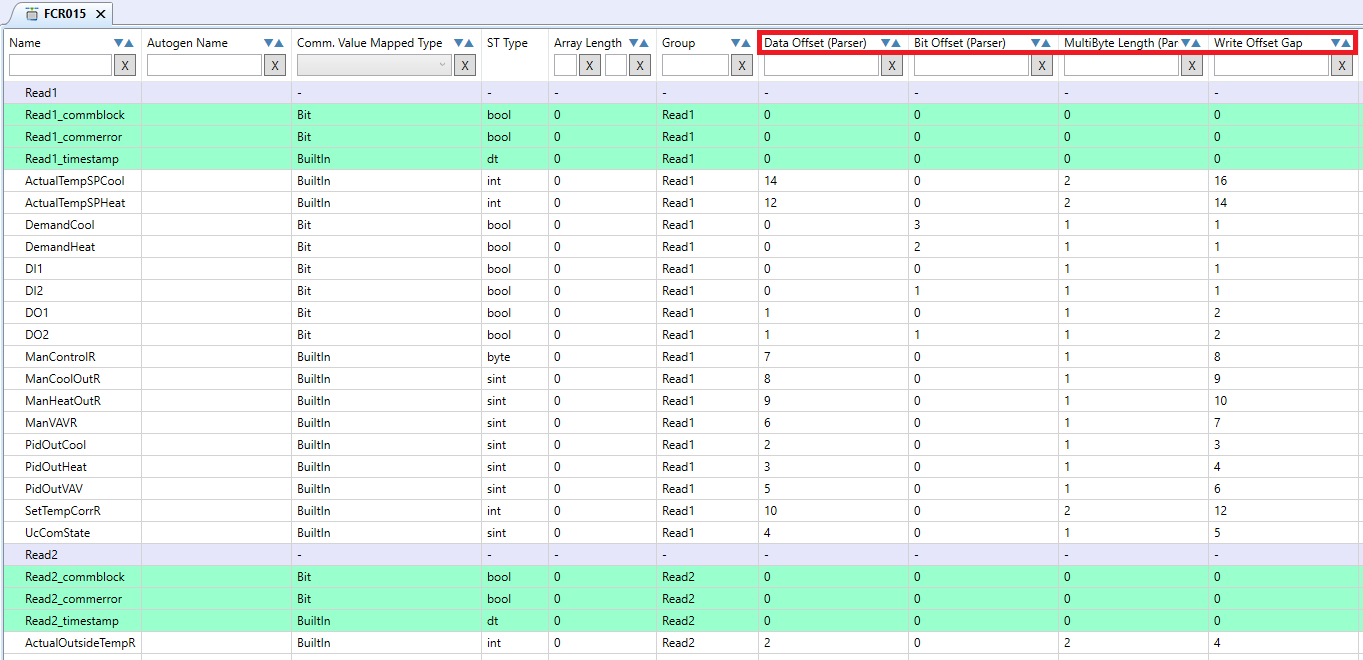
To map the Modbus parameters more efficiently and faster, they can be edited right from the communication channel editor. The edisor is displayed by double click on the communication channel or right click to the communication channel + Open editor.
The “Data Offset”, “Bit offset”, “MultiByte Length” and “Write offset gap” allow faster editing of Modbus parameters.
Modbus device export
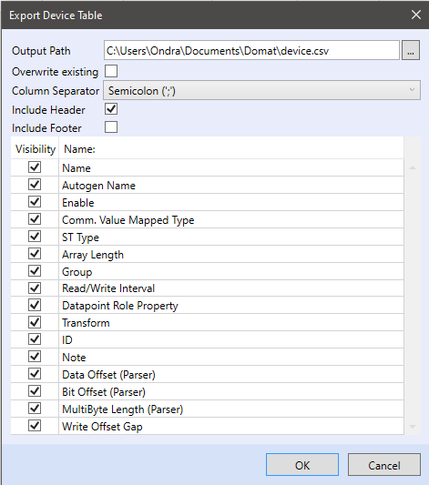
To export a Modbus device to a CSV file, right click the Device - Export device.
- Output Path - The target file path for export
- Overwrite existing - Replace an existing file if present
- Column separator - Colon, Semicolon, or Tab.
- Include Header - The header contains items checked below
- Include Footer - The footer contains items checked below
